1. Kupu Whakataki
This manual provides comprehensive instructions for the DROK Adjustable Current Voltage Analog Simulator Signal Generator, Model 300482_JPN. This versatile module is designed to generate both 0/4-20mA current signals and 0-10V voltage signals, making it suitable for a wide range of industrial and testing applications. Please read this manual carefully before operation to ensure proper use and to prevent damage.
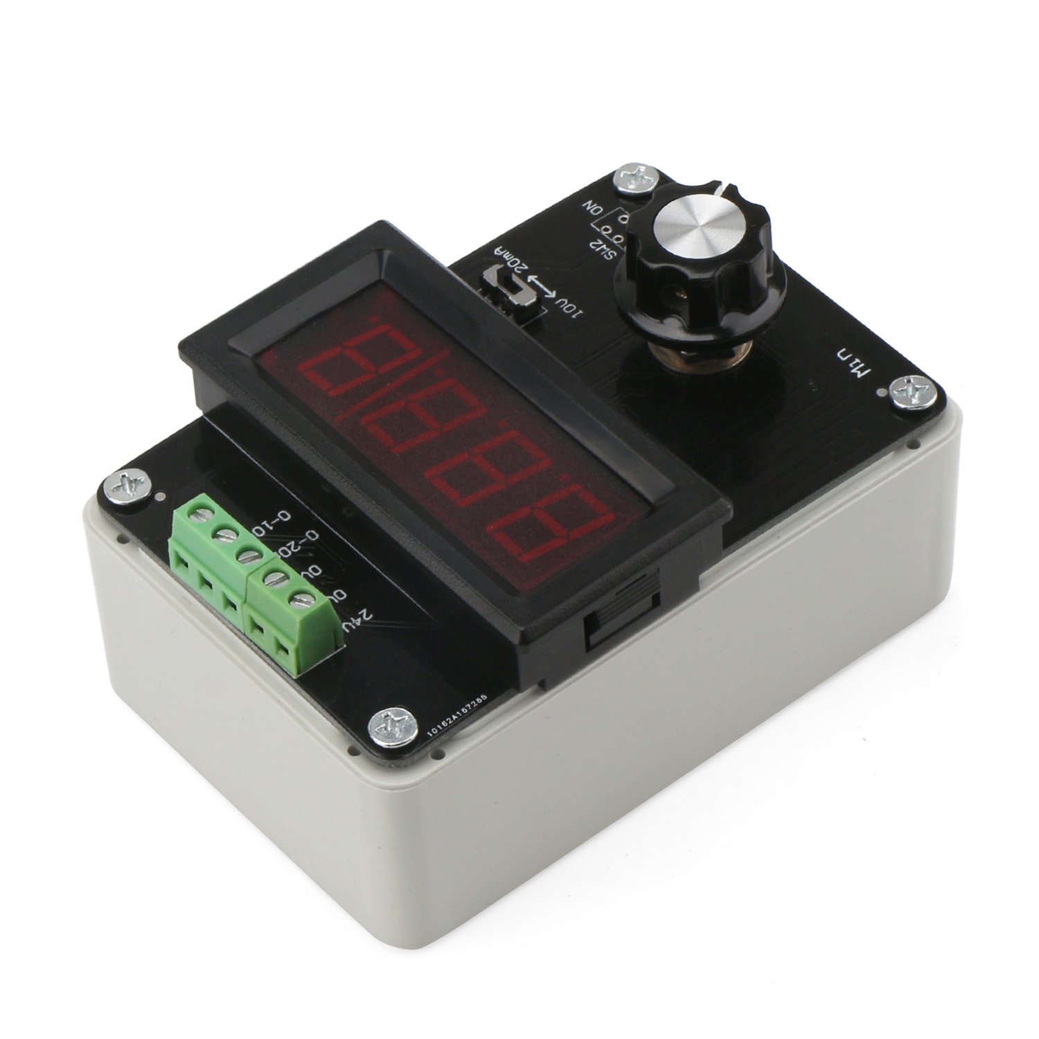
Whakaahua 1: Runga-raro view of the DROK Signal Generator, showing the digital display, control knob, and terminal block.
2. Whakatakotoranga
| Tawhā | Uara |
|---|---|
| Mahinga Mahi Voltage | DC 12-24V |
| Waitohu Input | Potentiometer (for adjustment) |
| Waitohu Huaputa | 0/4-20mA (Current) or 0-10V (Voltage) |
| Current Display Accuracy | 0.1mA |
| Voltage Whakaaturanga Tika | 0.01V |
| Ahu (L x W x H) | 100mm x 68mm x 38mm |
| Taumaha Hua | 130g |
| Tau Waahanga Kaihanga | 300482_JPN |

Image 2: Dimensions of the DROK Signal Generator, illustrating its compact size.
3. Nga Hua o te Hua
- Dual Signal Output: Generates both 0/4-20mA current signals and 0-10V voltage signals from a single module.
- Putanga Whakarite: Output signals are precisely adjustable using a multi-cycle potentiometer.
- Maama Whakaaturanga LED: Features a bright, clear 3-digit LED digital display for real-time monitoring of output current and voltage.
- Easy Display Switching: A dedicated switch allows for quick toggling between current and voltage display modes.
- Whakaaturanga Whakatau: Includes calibration potentiometers on the module's rear for fine-tuning the current and voltage display accuracy.
- Taupānga Whānui: Suitable for signal generation, valve adjustment, inverter control, PLC debugging, panel debugging, LED testing, and transmitter output simulation.
4. Tatūnga
Before operating the signal generator, ensure proper power supply connection and output wiring.
- Hononga Tuku Hiko: Connect a DC 12-24V power source to the designated power input terminals (typically labeled '24V' and 'GND' or similar) on the terminal block. Ensure correct polarity.
- Waea Putanga: Connect your target device or multimeter to the appropriate output terminals. For current output, use the '0-20mA' terminals. For voltage output, use the '0-10V' terminals. Refer to the terminal block labels for precise connections.
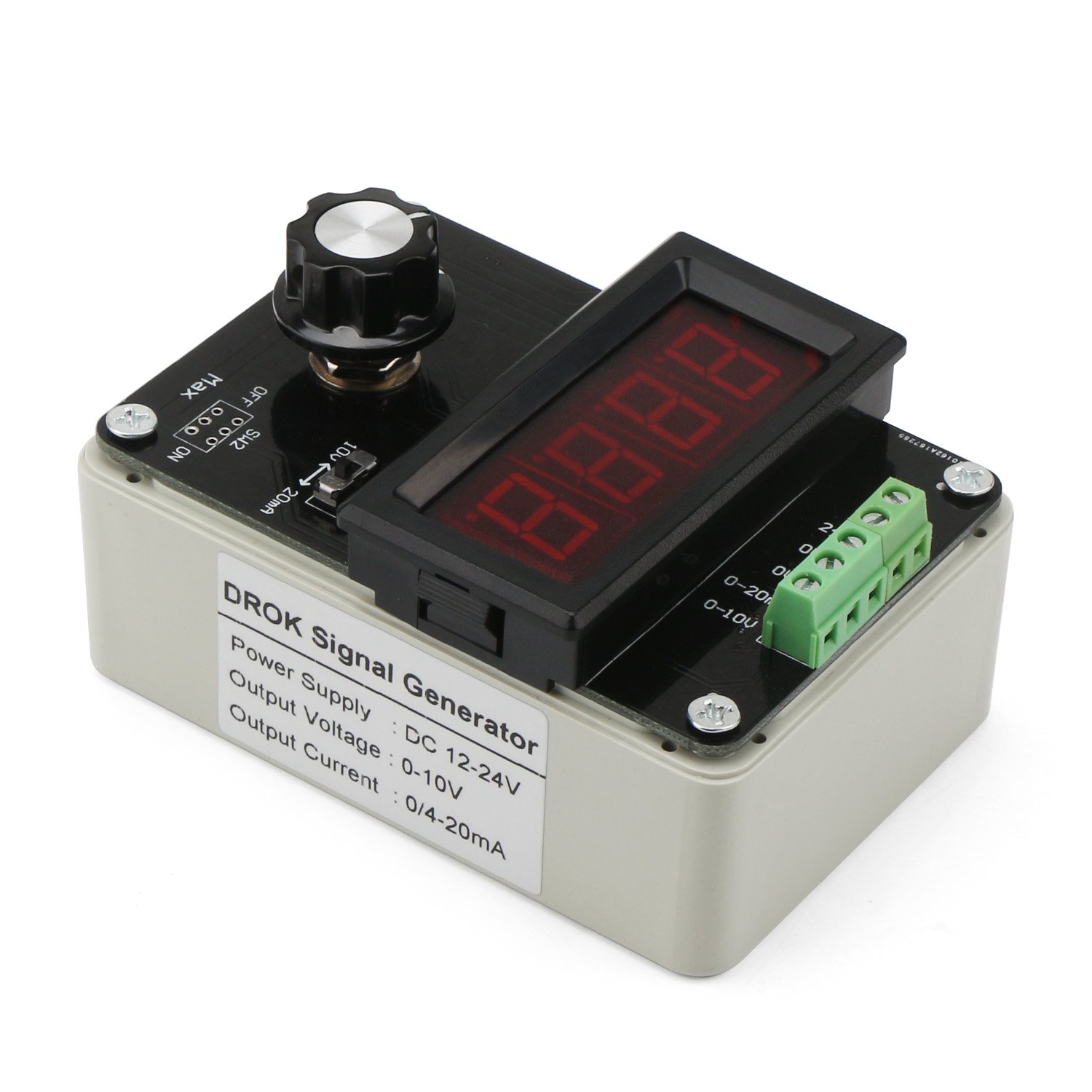
Whakaahua 3: Whakamuri view of the DROK Signal Generator, showing the power supply and output voltage/current labels.
5. Mahi
The signal generator features a main control knob and a display switch for easy operation.
- Whakahiko: Once connected to a DC 12-24V power supply, the LED display will illuminate.
- Select Output Type: Use the slide switch (labeled SW1 or similar) to select between voltage output (0-10V) or current output (0/4-20mA). The switch position will typically be indicated by labels such as '10V' for voltage and '20mA' for current.
- Adjust Output Value: Rotate the multi-cycle potentiometer knob (labeled 'Min' to 'Max') to adjust the desired output signal. Turning the knob clockwise increases the output, and counter-clockwise decreases it.
- Whakawhiti Aratau Whakaatu: Press the button located below the LED display to toggle between displaying the output current and output voltage.

Image 4: Labeled diagram of the control panel. It shows the 3-digit digital display, the current/voltage display switch (left for voltage, right for current), and the multi-cycle adjustable potentiometer.
6. Whakaatu Whakatau
The module includes calibration potentiometers on the back to ensure the displayed values match the actual output. A multimeter is required for accurate calibration.
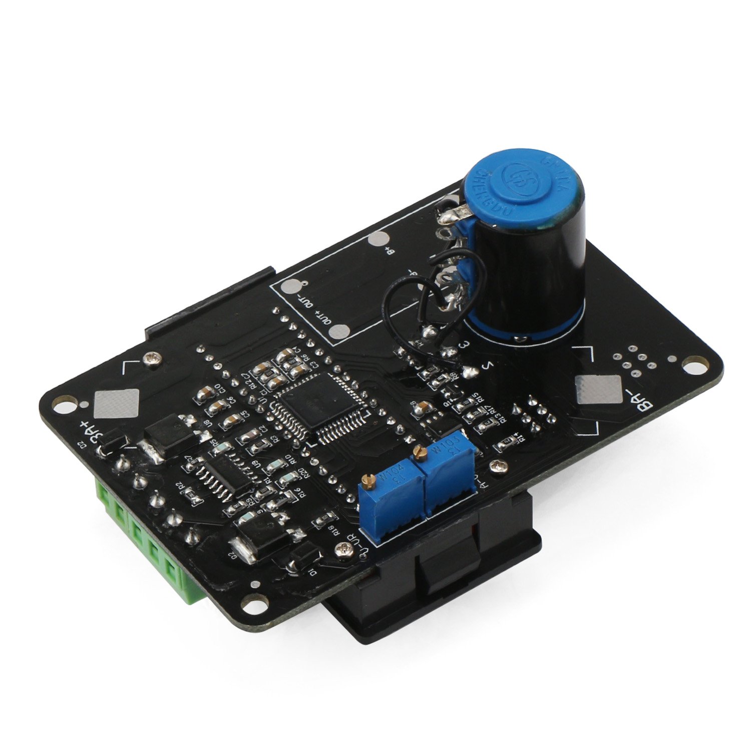
Whakaahua 5: Raro view of the DROK Signal Generator PCB, highlighting the two blue calibration potentiometers for current and voltage display adjustment.
6.1. Current Display Calibration
- Rotate the main multi-cycle potentiometer knob clockwise to its maximum output.
- Set the output type switch (SW1) to the current output position (e.g., '20mA').
- Use an external multimeter to measure the actual output current value from the '0-20mA' terminals.
- Adjust the current display adjustment potentiometer (located on the back of the module, refer to Image 5) until the value shown on the module's LED display matches the actual current value measured by the multimeter.
6.2. Rererangitage Display Calibration
- Rotate the main multi-cycle potentiometer knob clockwise to its maximum output.
- Set the output type switch (SW1) to the voltage output position (e.g., '10V').
- Use an external multimeter to measure the actual output voltage value from the '0-10V' terminals.
- Whakaritea te voltage display adjustment potentiometer (located on the back of the module, refer to Image 5) until the value shown on the module's LED display matches the actual voltage value measured by the multimeter.
7. Nga tono
The DROK Signal Generator is suitable for various applications, including but not limited to:
- General signal generation for testing and development.
- Valve adjustment and control.
- Inverter control systems.
- PLC (Programmable Logic Controller) debugging.
- Panel debugging and testing.
- LED testing and characterization.
- Transmitter output simulation.
8. Te Raru
| Raruraru | Take pea | Rongoā |
|---|---|---|
| Kāore he whakaaturanga/Kāore he hiko | Putanga hiko hē voltage or polarity; Loose connection. | Verify DC 12-24V power supply. Check power cable connections and polarity. |
| Output value does not change | Potentiometer not adjusted; Output type switch in wrong position. | Rotate the main potentiometer. Ensure the output type switch (SW1) is set correctly for current or voltage. |
| Displayed value is inaccurate | Display requires calibration. | Perform display calibration as described in Section 6 using an external multimeter. |
| Kaore he tohu whakaputa | Incorrect wiring; Faulty connection to target device. | Check output wiring to the target device. Ensure the device is correctly configured to receive the signal. |
9. Ihirangi mokete
The package for Model 300482_JPN typically includes:
- 1 x DROK Adjustable Current Voltage Analog Simulator Signal Generator
10. Pūtāhui me te Tautoko
For warranty information or technical support, please refer to the product's purchase platform or contact DROK customer service directly. Keep your purchase receipt for warranty claims.