1. Kupu Whakataki
The Velleman DVM810 is a compact and economical 3 1/2 digit digital multimeter designed for measuring DC and AC voltages, DC currents, resistance, and for performing diode and transistor (hFE) tests. It features overload protection and automatic polarity indication, making it suitable for hobbyists, field use, and workshops. This manual provides essential information for the safe and effective operation of your DVM810 multimeter.
2. Nga Hua o te Hua
- Automatic polarity indication
- Voltage measurements: AC 500V and DC 500V maximum
- Current measurements: DC 10A maximum (0.2A fused, 10A unfused)
- Resistance measurements: Up to 2MΩ
- Diode and transistor (hFE) test functions
- Te parenga taumaha
- Compact design with 3 1/2 digit LCD display
3. Ihirangi mokete
Tena koa tirohia nga ihirangi o te kete kia mohio kei te noho katoa nga taonga:
- Velleman DVM810 Digital Multimeter
- Nga Tohu Whakamatau (kotahi te whero, kotahi te pango)
- Pukapuka Tohutohu
4. Nga Korero Haumaru Nui
Read all safety warnings and instructions carefully before using this product. Failure to follow these instructions may result in electric shock, fire, or serious injury.
- Always ensure the multimeter is set to the correct function and range before making any measurements.
- Never exceed the maximum input limits for any range. The maximum voltage for AC/DC is 500V.
- Do not attempt to measure current on circuits with voltagneke atu i te 250V.
- Inspect test leads for damaged insulation or exposed metal before each use. Replace damaged leads immediately.
- Kaua e whakamahia te mita maha mēnā kua pakaru te āhua, kua tuwhera rānei te pouaka.
- Exercise extreme caution when working with live circuits. Use appropriate personal protective equipment.
- Always disconnect power to the circuit and discharge high-voltage capacitors before measuring resistance or performing diode/transistor tests.
- Replace the battery when the low battery indicator appears on the display to ensure accurate readings.
5. Hua Neke Atuview
Familiarize yourself with the components of your Velleman DVM810 multimeter:
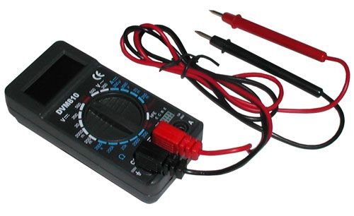
Figure 1: Velleman DVM810 Digital Multimeter. This image displays the front view of the compact multimeter, highlighting its liquid crystal display (LCD), the central rotary function switch, and the input jacks for test leads at the bottom.
- Whakaaturanga LCD: Shows measurement readings, units, and polarity.
- Whakawhiti Rotary: Whakamahia hei tīpako i te mahi ine me te awhe e hiahiatia ana.
- Ngā Jack Tāuru:
- COM Jack: Common (negative) input for all measurements. Connect the black test lead here.
- Tūhono VΩmA: Tāuru pai mō te rōrahitage, resistance, and current measurements up to 200mA. Connect the red test lead here.
- 10A Jack: Positive input for high current measurements (up to 10A). Connect the red test lead here for 10A measurements.
- Nga Tohu Whakamatau: He taura whero me te mangu e whakamahia ana hei hono i te mita maha ki te ara iahiko e whakamatautauria ana.
6. Tatūnga
6.1 Tāuta Pūhiko
The DVM810 multimeter requires a 9V battery (not always included). To install or replace the battery:
- Ensure the multimeter is turned OFF (rotary switch set to OFF).
- Kimihia te uhi o te wahanga pākahiko kei muri o te waeine.
- Tangohia te tīwiri e mau ana i te taupoki, ka ata hiki ake.
- Honoa he pākahiko 9V hou ki te topenga pākahiko, me te tirotiro tonu i te polarity tika.
- Whakatakotoria te pākahiko ki roto i te wāhanga ka whakahokia te taupoki, me te whakau ki te/ngā tīwiri.
6.2 Te hono i nga kaiarahi Whakamātautau
Always connect the test leads correctly for accurate and safe measurements:
- Whakauruhia te mata whakamatautau pango ki roto i te COM (common) jack.
- Mo te nuinga o nga inenga (voltage, resistance, diode, hFE, and current up to 200mA), insert the red test lead into the VΩmA koki.
- Mō ngā inenga au teitei (tae atu ki te 10A), whakauruhia te taura whakamātautau whero ki roto i te 10A koki.
7. Nga Tohutohu Whakahaere
Before making any measurement, ensure the test leads are correctly connected and the rotary switch is set to the appropriate function and range.
7.1 Te Ine DC Voltage (V=)
- Whakauruhia te mata whero ki roto i te VΩmA jack and the black lead into the COM koki.
- Whakatakotoria te pana hurihuri ki te DC Voltage e hiahiatia anatage (V=) range. Start with the highest range if the voltage kore e mohiotia.
- Connect the test leads across the component or circuit to be measured (in parallel).
- Pānuihia te voltage value on the LCD display. The display will show the correct polarity.
7.2 Te Ine AC Voltage (V~)
- Whakauruhia te mata whero ki roto i te VΩmA jack and the black lead into the COM koki.
- Tautuhia te huri hurihuri ki te Vol AC e hiahiatia anatage (V~) range. Start with the highest range if the voltage kore e mohiotia.
- Connect the test leads across the component or circuit to be measured (in parallel).
- Pānuihia te voltage uara i runga i te whakaaturanga LCD.
7.3 Te Ine i te Iahiko DC (A=)
Caution: Never connect the multimeter in parallel with a voltagte pūtake i te wā e ine ana i te iahiko, nā te mea ka pakaru te fuse, ka kino rānei te mita.
- Determine the expected current. For currents up to 200mA, insert the red lead into the VΩmA jack. For currents up to 10A, insert the red lead into the 10A jack. Always insert the black lead into the COM koki.
- Set the rotary switch to the appropriate DC Current (A=) range. Start with the highest range if the current is unknown.
- Turn off power to the circuit. Open the circuit where the current is to be measured.
- Honoa te mita maha ki te ara iahiko mā te raupapa.
- Restore power to the circuit and read the current value on the LCD display.
7.4 Te Ine i te Ātete (Ω)
Caution: Ensure the circuit is completely de-energized and all capacitors are discharged before measuring resistance.
- Whakauruhia te mata whero ki roto i te VΩmA jack and the black lead into the COM koki.
- Set the rotary switch to the desired Resistance (Ω) range. Start with a higher range if the resistance is unknown.
- Honoa nga arataki whakamatautau puta noa i te waahanga hei ine.
- Pānuihia te uara ātete i runga i te mata LCD.
7.5 Whakatautau Diode
Caution: Ensure the diode is disconnected from the circuit or the circuit is de-energized before testing.
- Whakauruhia te mata whero ki roto i te VΩmA jack and the black lead into the COM koki.
- Set the rotary switch to the Diode symbol (→|).
- Connect the red lead to the anode and the black lead to the cathode of the diode. The display will show the forward voltagte maturuturunga hiko (te tikanga 0.5V ki te 0.8V mō ngā taio hiko silicon).
- Reverse the leads. The display should show 'OL' (Overload) for a good diode. If it shows a reading in both directions or 'OL' in both directions, the diode may be faulty.
7.6 Transistor (hFE) Test
Caution: Ensure the transistor is disconnected from the circuit before testing.
- Whakauruhia te mata whero ki roto i te VΩmA jack and the black lead into the COM koki.
- Tautuhia te huri hurihuri ki te tuunga hFE.
- Identify if the transistor is NPN or PNP. Insert the transistor's emitter, base, and collector leads into the corresponding holes in the hFE socket on the multimeter.
- Pānuihia te uara hFE (whakanui i te iahiko DC) i runga i te mata LCD.
8. Whakatakotoranga
| Tawhā | Uara |
|---|---|
| Waitohu | Kawana |
| Tau tauira | DVM810 |
| Momo Ine | Imita maha |
| DC Voltage Awhe | Tae atu ki te 500V |
| AC Voltage Awhe | Tae atu ki te 500V |
| DC Awhe o Naianei | Up to 10A (0.2A fused, 10A unfused) |
| Awhe Ātete | Up to 2MΩ |
| Whakamatau Diode | Ae |
| Transistor (hFE) Test | Ae |
| Whakaatu | 3 1/2 Digit LCD |
| Puna Mana | Pūhiko 9V (kāore i roto) |
| Ahu | Tata ki te 3.70" x 1.81" x 1.03" |
| Taumaha Tūemi | Tata ki te 3.2 hekere (0.2 lbs) |
| UPC | 836479002272 |
9. Tiaki
9.1 Whakakapinga Pūhiko
When the low battery indicator appears on the LCD, replace the 9V battery as described in Section 6.1. A weak battery can lead to inaccurate readings.
9.2 Te horoi
Hei horoi i te mita maha, murua te pouaka ki te adamp cloth and a mild detergent. Do not use abrasives or solvents. Ensure the unit is completely dry before use.
9.3 Te Tirotiro Arahi Whakamatau
Tirohia tonutia ngā taura whakamātautau mō ngā tohu pakaru, pērā i te pakaru o te ārai hiko, ngā waea e kitea ana, ngā hononga ngoikore rānei. Whakakapia tonutia ngā taura pakaru hei ārai i ngā tūponotanga o te ru hiko.
10. Te Raru
- Kāore he whakaaturanga, he whakaaturanga ngoikore rānei: Tirohia te pākahiko. Whakakapia mēnā e tika ana.
- Ngā pānui hē:
- Ensure the rotary switch is set to the correct function and range.
- Tirohia te puhiko voltage; replace if low.
- Me whakarite kia hono tika ngā taura whakamātautau, ā, kia kaua e pakaru.
- For resistance measurements, ensure the circuit is de-energized.
- 'OL' (Taumaha rawa) e whakaaturia ana: Kua hipa te uara ine i te awhe kua tīpakohia. Kōwhiria he awhe teitei ake, kia mōhio rānei kei roto te ara iahiko i ngā āheinga o te mita.
- Fuse blown (during current measurement): If the meter stops measuring current, the internal fuse may have blown. Refer to a qualified technician for fuse replacement.
11. Pūtāhui me te Tautoko
Warranty information for the Velleman DVM810 Digital Multimeter is typically provided with your purchase documentation or can be found on the official Velleman website. For technical support, service, or further inquiries, please refer to the contact information provided by your retailer or the manufacturer's official support channels.


