1. Kupu Whakataki
This manual provides comprehensive instructions for the installation, operation, and maintenance of the Supermicro X10SLM+-LN4F motherboard. Designed for server applications, this motherboard features an LGA1150 socket, Intel C224 PCH, DDR3 memory support, and multiple Gigabit Ethernet ports. Please read this manual thoroughly before proceeding with installation to ensure proper setup and optimal performance.
2. Hua Neke Atuview
The Supermicro X10SLM+-LN4F is a microATX server motherboard built for reliability and performance. Key features include:
- LGA1150 Socket for Intel Xeon E3-1200 v3/v4 and 4th Gen Core i3 processors.
- Intel C224 PCH chipset.
- Four DDR3 DIMM slots supporting up to 64GB ECC/non-ECC UDIMM.
- Multiple SATA3 (6Gbps) ports.
- Integrated quad Gigabit Ethernet ports.
- USB 3.0 and USB 2.0 support.
- VGA output for integrated graphics.
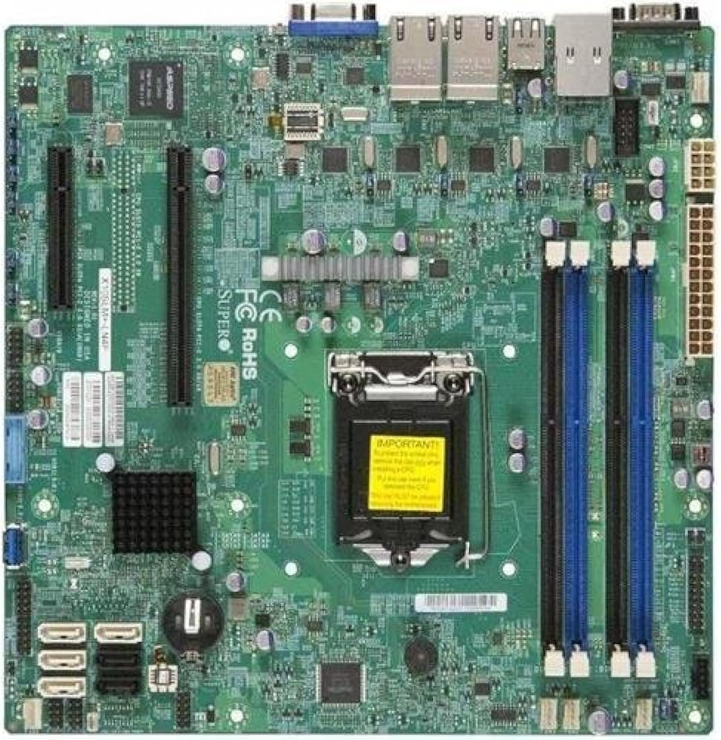
Whakaahua 2.1: runga-iho view of the Supermicro X10SLM+-LN4F motherboard, showing the CPU socket, DIMM slots, PCIe slots, and various connectors.

Whakaahua 2.2: Koki view of the motherboard, highlighting the layout of components and expansion slots.
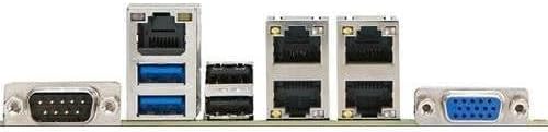
Whakaahua 2.3: Rear I/O panel of the Supermicro X10SLM+-LN4F motherboard, featuring multiple LAN ports, USB ports, and serial ports.
3. Tatūnga me te Tāuta
Before beginning installation, ensure your system is powered off and disconnected from the power source. Wear an anti-static wrist strap to prevent electrostatic discharge (ESD) damage to components.
3.1. Tāuta PTM
- Kimihia te turanga PTM LGA1150 i runga i te papahoa papa.
- Pēhia mārire te rīwhi kawenga ki raro, ka tōia ki te taha hei whakatuwhera i te anga pupuri o te putanga CPU.
- Āta whakarārangihia te tohu tapatoru i runga i te CPU ki te tohu e rite ana i runga i te putanga.
- Whakanohoia te CPU ki roto i te putanga, kaua e akiakihia.
- Close the retention frame and secure it with the load lever.
- Hoatu he paparanga angiangi o te whakapiri waiariki ki te horapa wera whakauru o te PTM (IHS).
- Tāutahia te whakamatao CPU kia rite ki nga tohutohu a te kaihanga.
3.2. Mahara (RAM) Tāutatanga
- Locate the four DDR3 DIMM slots. For optimal performance, refer to the motherboard's specific memory population guidelines, typically starting with slots closest to the CPU or specific colored slots for dual-channel configurations.
- Whakatuwheratia nga topenga pupuri i nga pito e rua o te mokamoka DIMM.
- Tiarohia te kakari ki te kōwae mahara DDR3 me te kī i roto i te mokamoka DIMM.
- Insert the memory module firmly into the slot until the retention clips snap into place.
- Ensure both clips are fully closed and the module is seated correctly.
3.3. Tāuta Pūrere Rokiroki
Connect SATA storage devices (HDDs/SSDs) to the SATA ports on the motherboard using SATA data cables. Connect the power cables from your power supply unit (PSU) to the storage devices.
3.4. Tāutatanga Kāri Whakawhānui
This motherboard features PCI Express (PCIe) slots. To install an expansion card:
- Remove the corresponding slot cover from your chassis.
- Whakahāngaihia te kāri whakawhanui ki te mokamoka PCIe.
- Pēhia kia kaha te pēhi kia tino uru te kāri ki roto i te mokowā.
- Secure the card with a screw or retention clip from your chassis.
3.5. Hononga Hiko
- Tūhono Hiko ATX 24-pin: Connect the main 24-pin power cable from your PSU to the ATX power connector on the motherboard.
- 8-pin EPS/CPU Power Connector: Connect the 8-pin (or 4+4 pin) CPU power cable from your PSU to the EPS connector near the CPU socket.
3.6. Paewhiri Mua me nga Hononga I/O muri
- Tūhono Paewhiri Mua: Connect the power switch, reset switch, power LED, and HDD activity LED cables from your chassis to the corresponding pins on the motherboard's front panel header. Refer to the motherboard's silkscreen labels for correct orientation.
- Pane USB: Connect front panel USB ports to the onboard USB headers.
- Pane Ororongo: Connect front panel audio jacks to the onboard audio header.
- Paepae I/O muri: Connect peripherals such as keyboard, mouse, monitor (via VGA), and network cables (to the Gigabit Ethernet ports) to the rear I/O panel.
4. Nga Tohutohu Whakahaere
4.1. Initial Power On and BIOS/UEFI Setup
- After all components are installed and connected, connect the power cord to the PSU and turn on the power switch on the PSU.
- Press the power button on your chassis.
- During the Power-On Self-Test (POST), repeatedly press the DEL or F2 kī (kia tohuhia ranei i runga i te mata) hei whakauru i te taputapu tatūnga BIOS/UEFI.
- In the BIOS/UEFI, configure essential settings such as date and time, boot order, and enable/disable specific features as required for your operating system and hardware.
- Tiakina ngā huringa ka puta atu i te BIOS/UEFI. Ka tīmata anō te pūnaha.
4.2. Tāuta Pūnaha Whakahaere
To install an operating system (e.g., Windows, Linux, VMware ESXi):
- Insert the operating system installation media (USB drive or DVD) into the system.
- Boot from the installation media (you may need to adjust the boot order in BIOS/UEFI).
- Follow the on-screen prompts to install the operating system on your chosen storage device.
- After installation, install all necessary drivers for the motherboard components (chipset, LAN, VGA, etc.) from the Supermicro website or the provided driver disc.
5. Tiaki
Mā te tiaki auau ka roa te mahi me te pumau o tō papahoahoa me tō pūnaha.
5.1. Te horoi
- Periodically clean dust from the motherboard and system components using compressed air. Ensure the system is powered off and unplugged before cleaning.
- Āta karohia te whakamahi i ngā wai horoi tika ki ngā wāhanga.
- Ensure proper airflow within the chassis by keeping fan vents clear.
5.2. Firmware and Driver Updates
- Tirohia te Supermicro website periodically for updated BIOS/UEFI firmware and drivers for your motherboard model.
- Follow the provided instructions carefully when updating firmware to avoid system instability.
5.3. Nga Whakaaro Taiao
- Whakahaerehia te papahoahoa i roto i ngā awhe pāmahana me te haumākū e taunakitia ana hei ārai i te kino.
- Ensure adequate ventilation in the server chassis.
6. Te Raru
Ko tenei waahanga e whakarato ana i nga otinga mo nga take noa ka pa ki a koe.
6.1. No Power / No POST (Power-On Self-Test)
- Verify that the power supply unit (PSU) is connected correctly to the motherboard (24-pin ATX and 8-pin EPS connectors).
- Ensure the PSU is switched on and receiving power from the wall outlet.
- Tirohia kei te tika te hono o te taura whakawhiti hiko o mua ki te pane papahoa.
- Reseat the CPU, RAM modules, and any expansion cards.
- Ngāna ki te whakaara anō me ngā wāhanga matua anake (CPU, tētahi rākau RAM, he whakamatao CPU) hei tautuhi i te raruraru.
- Listen for beep codes from the system speaker, which can indicate specific hardware failures. Refer to the Supermicro webpae tukutuku mō ngā whakamāoritanga waehere pī.
6.2. Whakaatu Take
- Ensure the monitor is properly connected to the motherboard's VGA port.
- Manatokohia kei te kā te mata, ā, kei te whakatakotoria ki te pūtake tāuru tika.
- If using a discrete graphics card, ensure it is properly seated and connected to power (if required).
6.3. Operating System Not Booting
- Check the boot order in the BIOS/UEFI to ensure the correct storage device is prioritized.
- Verify that the operating system is installed correctly on the storage device.
- Ensure SATA data and power cables are securely connected to the storage device and motherboard.
7. Whakatakotoranga
Below are the technical specifications for the Supermicro X10SLM+-LN4F motherboard:
| Āhuahira | Taipitopito |
|---|---|
| Waitohu | Supermicro |
| Ingoa Tauira | X10SLM+-LN4F-B |
| Putunga PTM | LGA1150 |
| Momo Chipset | Intel C224 |
| Hangarau Mahara RAM | DDR3 SDRAM |
| Tere Mahara | 1600 MHz |
| Te Rokiroki Mahara | Tae atu ki te 64 GB |
| Te maha o nga Tauranga USB 2.0 | 2 (Pūnaha Whakauru/Whakamuri) |
| Atanga Kaari Whakairoiro | Integrated, PCI |
| Pūrere Hototahi | Tūmau |
| Paerewa | Matapihi 10 |
| Taumaha Tūemi | 5.8 pauna |
| Rahi Hua (LxWxH) | 10 x 10 x 2 inihi |
| Te Ra Tuatahi Wātea | Pipiri 4, 2013 |
Note: Specifications are subject to change without notice. For the most current information, please refer to the official Supermicro product page.
8. Pūtāhui me te Tautoko
For detailed warranty information, please refer to the warranty card included with your product or visit the official Supermicro website. Technical support is available through Supermicro's customer service channels, including their support portal, email, and phone. Please have your product model number (X10SLM+-LN4F) and serial number ready when contacting support.
For the latest drivers, BIOS updates, and additional documentation, please visit: www.hewhitu.ro


