1. Kupu Whakataki
This manual provides detailed instructions for the installation, operation, and maintenance of the Supermicro MBD-X10SLH-F-O uATX Server Motherboard. Please read this manual thoroughly before beginning installation to ensure proper setup and to maximize the performance and longevity of your system. This motherboard is designed for server applications, supporting Intel LGA1150 processors and DDR3 memory.
2. Hua Neke Atuview
The Supermicro MBD-X10SLH-F-O is a high-performance uATX server motherboard featuring the Intel C226 chipset. It is engineered for reliability and efficiency in server environments.
Āhuatanga matua:
- Kopae CPU: LGA1150, supporting Intel Xeon E3-1200 v3/v4 series, 4th/5th Gen Core i3, Pentium, Celeron processors.
- Pūmahara: 4x 204-pin DDR3-1600 SODIMM slots, supporting up to 32GB ECC/non-ECC Unbuffered memory.
- Roha i'ai: 1x PCI-Express 3.0 x16, 1x PCI-Express 2.0 x8, 1x PCI-Express 2.0 x4.
- Rokiroki: 6x SATA3 (6Gbps) ports.
- Hononga: Dual Gigabit Ethernet LAN ports (2x RJ45) and 1x Dedicated IPMI LAN port (RJ45).
- Tauranga USB: 4x USB 3.0 ports, 6x USB 2.0 ports.
- Putanga Ataata: 1x VGA port.
- Tauwehe Puka: uATX (9.6" x 9.6").
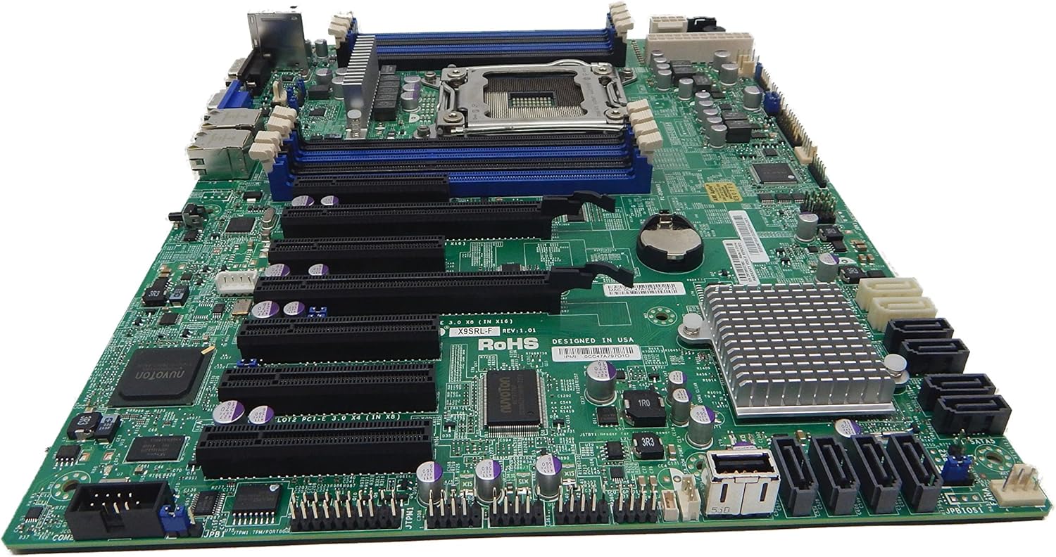
Whakaahua 2.1: runga-iho view of the Supermicro MBD-X10SLH-F-O motherboard, showing the CPU socket, RAM slots, and various expansion slots.

Whakaahua 2.2: Koki view of the motherboard, highlighting the LGA1150 CPU socket and the four DDR3 SODIMM memory slots.

Whakaahua 2.3: Whakamuri view of the Supermicro MBD-X10SLH-F-O motherboard, displaying the I/O panel with USB, VGA, LAN, and IPMI ports.

Whakaahua 2.4: Kati-ake view of the motherboard, showing the six SATA3 ports and other onboard connectors.
3. Whakatakotoranga
| Āhuahira | Whakatakotoranga |
|---|---|
| Waitohu | Supermicro |
| Ingoa Tauira | MBD-X10SLH-F-O |
| Putunga PTM | LGA 1150 |
| Momo Chipset | Intel C226 |
| Tukatuka Hototahi | Intel Core i3-4xxx, i5-4xxx, i7-4xxx, i3-5xxx, i5-5xxx, i7-5xxx, Intel Xeon E3-1200 v3/v4 series |
| Hangarau Mahara RAM | DDR3 |
| Tere Mahara | 1600 MHz |
| Max RAM Supported | 32 GB |
| Te maha o nga Tauranga USB 2.0 | 6 |
| Te maha o nga Tauranga USB 3.0 | 4 |
| Tauranga SATA | 6x SATA3 (6Gbps) |
| Roha Slots | 1x PCIe 3.0 x16, 1x PCIe 2.0 x8, 1x PCIe 2.0 x4 |
| Tauwehe Puka | uATX |
| Ahu (LxWxH) | 14 x 11 x 3.5 inihi |
| Taumaha Tūemi | 3.52 hekere |
4. Tatūnga
Before beginning installation, ensure your system is powered off and disconnected from the power source. Always handle the motherboard by its edges to avoid static discharge.
4.1. Tāuta PTM
- Gently lift the CPU socket lever.
- Align the CPU with the socket, ensuring the gold triangle on the CPU matches the triangle on the socket.
- Āta whakanohoia te CPU ki roto i te putanga, kaua e akiaki.
- Lower the socket lever and secure it.
- Hoatuhia te whakapiri waiariki me te whakauru i te whakamatao CPU kia rite ki nga tohutohu a te kaihanga.
4.2. Memory Installation
- Whakatuwheratia nga topenga i nga pito e rua o te mokamoka DIMM.
- Whakahāngaihia te kokonga o te wae mahara ki te kī i roto i te mokamoka DIMM.
- Pēhia ki raro i ngā pito e rua o te kōwae mahara kia mau rā anō ngā topenga.
4.3. Tāutatanga Kāri Whakawhānui
- Remove the corresponding slot cover from your chassis.
- Align the expansion card with the desired PCIe slot.
- Press down firmly until the card is fully seated.
- Secure the card with a screw or retention clip.
4.4. Hononga Pūrere Rokiroki
- Honoa tetahi pito o te taura raraunga SATA ki te tauranga SATA i runga i te papahoahoa.
- Connect the other end of the SATA data cable to your storage device (HDD/SSD).
- Honoa he taura hiko SATA mai i tō pūtake hiko ki te pūrere rokiroki.
4.5. Hononga Hiko
- Tūhonoa te hononga hiko matua ATX 24-pin mai i tō pūtake hiko ki te papahoahoa.
- Connect the 8-pin (or 4-pin) ATX 12V CPU power connector to the motherboard.
4.6. Hononga Paewhiri Mua
Connect the front panel headers (Power LED, HDD LED, Power Switch, Reset Switch, USB, Audio) to the corresponding pins on the motherboard. Refer to the motherboard's silkscreen labels for correct pin orientation.
5. Nga Tohutohu Whakahaere
5.1. Whakaara Tuatahi
- After all components are installed and connected, connect the power cord to your power supply and turn on the power switch.
- Press the power button on your chassis.
- Me kaha te punaha, ka kite koe i tetahi whakaaturanga i runga i to kaitirotiro.
5.2. Urunga BIOS/UEFI
To enter the BIOS/UEFI setup utility, press the designated key (commonly DEL or F2) during the initial boot sequence. The exact key may vary; observe the on-screen prompts.
5.3. IPMI Remote Management
This motherboard features a dedicated IPMI LAN port for remote management. To access the IPMI interface, connect the IPMI LAN port to your network. Obtain the IP address assigned to the IPMI interface (either from BIOS or a network scan) and access it via a web browser from another computer on the same network. Java may be required for remote console functionality.
6. Tiaki
Regular maintenance helps ensure the stability and longevity of your motherboard and system.
- Tango Puehu: Me horoi i ia wa te puehu mai i te papahoa papa me nga waahanga ma te whakamahi i te hau kōpeke. Me mohio kua whakawetohia te punaha me te wetewete i te mono i mua i te horoi.
- Whakaha Uepu: Ensure all cables are neatly routed and secured to prevent obstruction of airflow and accidental disconnections.
- BIOS/Firmware Updates: Tirohia te Supermicro website for the latest BIOS and IPMI firmware updates. Follow the provided instructions carefully. Note that IPMI BIOS upgrades may require a separate license. Always update BIOS before IPMI firmware.
- Ngā Tirotiro Wāhanga: Occasionally inspect all connections (power, data, expansion cards) to ensure they are securely seated.
7. Te Raru
Ko tenei waahanga e aro ana ki nga take noa ka pa ki a koe.
7.1. System Fails to Boot
- Tirohia nga Hononga Hiko: Ensure the 24-pin ATX and 8-pin CPU power connectors are securely attached.
- Whakanohoia ano nga Wae: Remove and re-install the CPU, memory modules, and any expansion cards to ensure they are properly seated.
- Ūkui CMOS: Refer to your motherboard's detailed manual for instructions on how to clear the CMOS, which can resolve boot issues caused by incorrect BIOS settings.
- Whirihoranga iti: Try booting with only essential components (CPU, one RAM stick, power supply, and display) to isolate the problem.
7.2. Fan Speed Issues
Some low RPM, high-efficiency fans may not be accurately detected by the motherboard's fan controller, leading to erratic fan speed behavior (e.g., fans spinning up to max RPM). This is often due to the controller expecting server-grade fans with higher RPM ranges.
- Tautuhinga BIOS: Check BIOS settings for fan control options. Adjust fan curves or modes if available.
- 3-Pin vs. 4-Pin Fans: If using 4-pin PWM fans that exhibit this behavior, consider using 3-pin adapters if available with your fans. This can sometimes provide a more stable, albeit less precise, fan control.
- IPMI Fan Control: While IPMI offers fan control, it may have limitations for low RPM fans.
7.3. SATA Port Obstruction
When installing a full-size graphics processing unit (GPU), some SATA ports may become physically blocked or difficult to access.
- Mahere Amua: Connect SATA cables to the necessary ports before installing large expansion cards.
- Angled SATA Cables: Use SATA cables with angled connectors if straight connectors are obstructed.
- Alternative Ports: Utilize any unblocked SATA ports first.
8. Whakaputanga me nga korero tautoko
For detailed warranty information, including terms, conditions, and duration, please refer to the official Supermicro website or the warranty card included with your product. For technical support, driver downloads, and additional documentation, visit the Supermicro support portal.
Supermicro Official Webpae: www.hewhitu.ro


