Ka mutu te huaview
The Visionis FPC-7296 Four Door Access Control System provides robust security solutions for managing access to multiple entry points. This system includes a TCP/IP Wiegand controller, black card readers with keypads, 1200lbs magnetic locks for outswing doors, and accompanying software for user management and time attendance. It is designed for comprehensive access control and monitoring.
He aha kei roto
The FPC-7296 system includes the following components:
- (4) VIS-ML1200LED: 1200lbs Indoor Electric Magnetic Locks with LED Sensor.
- (4) VIS-3008: Access Control Black Outdoor IP66 Weather Proof Card Readers and Keypads. These standalone units support Wiegand 26-37 Bits, Delay and On/Off Toggle Mode, and 125KHz EM Cards. They support up to 1,000 PIN users (65 for PIN-only access) and up to 10,000 users via card or key-fob.
- (1) VS-AXESS-4ETL: Four Door Network Access Control Panel Controller Board with Cabinet, TCP/IP Wiegand, and Desktop Software. Supports up to 10,000 users. Power supply is included.
- (4) VIS-7013: Stainless Steel No-touch Request to Exit Buttons with Time Delay. Standard size with LED Light, NC, COM, and NO Outputs.
- (10) VS-VIS-APROXCARD/26: Access Control Proximity contactless Smart Entry cards (1.8mm thick, 26 bit, 125khz).
- (10) VS-VIS-KEYTAG: Access Control Proximity contactless Smart Entry Keyfobs (26 bit, 125khz).
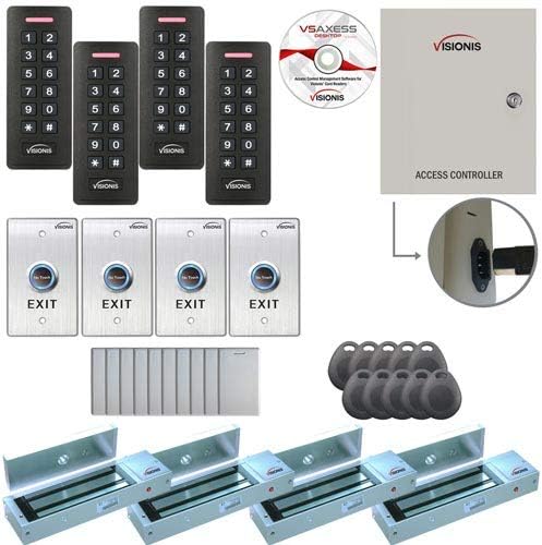
Whakaatu 1: Neke Atuview of the Visionis FPC-7296 Access Control System components, including magnetic locks, card readers, controller, exit buttons, and access credentials.

Figure 2: Close-up of the Visionis VIS-3008 Black Card Reader and Keypad, showing the numeric keypad and card reader area.
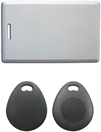
Whakaahua 3: Example of the Visionis Access Control Proximity Cards and Keyfobs used for user authentication.
Nga Korero Haumaru Nui
WHAKATOKANGA:
I mua i te hokoasing or installing this kit, it's recommended that the customer checks with their local fire authority to see if there is any additional product they may need in order to comply with the local fire codes.
We are not responsible for the improper installation of our product(s) or any type of fees that can be incurred by not complying with your local fire authority.
If you are not handy with electrical components, please consult with a certified electrician or locksmith.
Please read this carefully before installing this kit. This part is very important before you install this kit.
Pūmanawa Hototahi
Please keep in mind that the included software is only compatible with Microsoft-based computers. If for whatever reason you did not receive the physical user manual or CD for software, please follow the instructions provided in the packaging to download the user manual and device software from the manufacturer's webpae.
Video 1: Visionis Access Control with Software Wiring VS AXESS. This video provides a comprehensive guide to the installation and programming of the access control system, including software setup. (Duration: 16:21)
Utauta e hiahiatia ana mo te whakauru
To install your Visionis FPC-7296 system, you will need the following tools:
- Small Flat End Screwdriver
- Medium Flat End Screwdriver
- Kopiripi Phillips Iti
- Waenga Phillips Screwdriver
- Tapare waea
- Drill
- Electrical Wire (18/4 or 22/4 gauge wire recommended for installation. 18/4 gauge wire is required for connecting the maglock, receiver, and exit button. 300 feet max.)
Te Whakatūnga Tuatahi me te Whakamōhiotanga
Before beginning the physical installation on your doors, it is highly recommended to place all products on a workbench and familiarize yourself with each unit. This allows for a better understanding of the components and their connections.
Video 2: Initial setup and familiarization with the system components on a workbench. (Excerpt from 0:56 to 0:59)
Controller Reset Procedure
To reset the control panel for any reason, you must first disconnect the panel from the power outlet. The panel should not be connected to the outlet during this procedure.
- Disconnect the control panel from the power outlet.
- Using a pair of pliers, carefully remove the black jumper from the panel's PCB board.
- Move the black jumper to the last jumper position on the PCB board.
- Reconnect the power cord to the power outlet. You will hear a long beep lasting for a couple of seconds (maximum one minute).
- Once the long beep has finished, unplug the power cord from the power outlet again.
- Grab the pliers and return the black jumper to its original position on the PCB board.
- Plug the power cord back into the power outlet.
You have now completed the resetting of your access control panel. Remember, this procedure is only done if necessary.
Video 3: Detailed steps on how to reset the controller. (Excerpt from 1:17 to 2:41)
Wiring the Readers to the Controller Box
It is very important to follow the diagram located on the inside of the controller box door for these steps. We will provide instructions to ensure correct wiring.
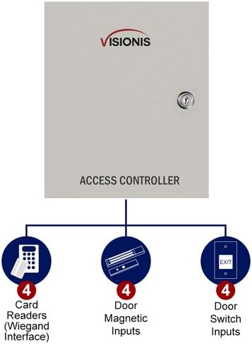
Figure 4: Wiring diagram for the Two Doors Access Controller, showing connections for card readers, exit buttons, and electromagnetic locks.
- Kāpeka 1: For door entry number one.
- Kāpeka 2: For door exit number one (used if installing a reader for exit purposes instead of an exit button). The connection remains the same as Terminal 1.
- Third Terminal Block: For the second door entry.
- Fourth Terminal Block: For the second door exit.
To wire the reader:
- Connect the brown wire from the reader to the "OK" terminal on the controller box (first terminal from left to right).
- Connect the yellow wire from the reader to the "BZ" terminal of the controller box (third terminal from left to right).
- Connect the white wire from the reader to the "W1" terminal on the controller box (fourth terminal from left to right).
- Connect the green wire from the reader to the "W0" terminal of the controller box (fifth terminal from left to right).
- Connect the black wire from the reader to the "GND" terminal of the controller box (seventh terminal from left to right).
- Connect the red wire from the reader to the "PWR" terminal of the controller box (sixth terminal from left to right).
Video 4: Step-by-step guide on how to wire the readers to the controller box. (Excerpt from 2:42 to 6:50)
Wiring the Exit Button to the Controller Box
We will demonstrate how to wire one exit button. You will connect all other exit buttons to their corresponding door terminals in the same way.
- Connect the white wire from the exit button to the "BUTTON" terminal on the controller (fourth terminal from right to left).
- Connect the green wire from the exit button to the "GND" terminal of the controller (fifth terminal from right to left). Keep this terminal slightly open to connect another wire.
- Connect one end of a separate wire to the black wire from the exit button. Connect the other end of this wire to the negative V terminal on the power supply (located underneath the PCB board).
- Connect one end of another separate wire to the red wire from the exit button. Connect the other end of this wire to the positive V terminal on the power supply (located underneath the PCB board).

Figure 5: Close-up of the Visionis VIS-7013 No-touch Request to Exit Button with its dimensions.
Video 5: Instructions on how to wire the exit button to the controller box. (Excerpt from 6:51 to 10:05)
Wiring the Magnetic Locks to the Controller Box
For starters, you will use the positive red wire and the negative black wire from the magnetic lock. We will show you how to connect one magnetic lock, but the connection remains the same for the other doors and terminals.

Figure 6: Close-up of the Visionis VIS-ML1200LED 1200lbs Indoor Electric Magnetic Lock with LED Sensor.
- Open the cap from the magnetic lock by unscrewing it with a Phillips screwdriver. The purpose of this step is so the lock can properly communicate the open or close status of the lock to the software.
- Connect one end of a wire to the normally open (NO) terminal of the magnetic lock (terminal number three from left to right).
- Connect the other end of this wire to the sensor terminal of the controller (terminal six from right to left).
- Connect the negative terminal of the magnetic lock to terminal two from left to right.
- Get a small piece of wire and do a wire bridge: connect one end of the wire to the common (COM) terminal of the magnetic lock (terminal five from left to right).
- Connect the positive red wire from the magnetic lock to the plus V terminal of the power supply (located underneath the PCB board).
Video 6: Detailed instructions on how to wire the magnetic locks to the controller box. (Excerpt from 11:07 to 14:24)
Connecting Power and LAN to the Controller
Before proceeding, ensure all your wires are securely connected using beanie connectors or black electrical tape.
- Temporarily un-wire the yellow cable from the reader to the controller. This step is crucial; if not completed, the controller will emit a long beep that will not stop when powered on.
- Connect one end of the LAN cable to the LAN port on the panel (located on the top left-hand side of the panel).
- Connect the other end of the LAN cable to your router.
- Plug the power cord from the controller box into an outlet.
You should now see lights on the panel, exit button, and reader, indicating power. Keep everything on. The next step involves configuring everything in the software.

Figure 7: The Visionis Access Control Panel showing the internal power supply and LAN connection port.
Video 7: Guide on connecting the power and LAN to the controller. (Excerpt from 14:25 to 16:10)
Later in the video, we will show you what to configure so you can plug the yellow wire back into the controller box.
If you do not have a UPS device for battery backup, you can purchase one for computers. This will provide power to the system in case of an outage.

Figure 8: Dimensions of the Visionis Access Control Panel.
Whakatakotoranga
- Kaihanga: Visionis
- Tau Wāhanga: FPC-7296
- Kāhua: 1200lbs Outswinging
- Pikohiko kei roto?: Kao
- Pikohiko e hiahiatia ana?: Kao
- ASIN: B07BWZWD6G
- Te Ra Tuatahi Wātea: Paenga-whāwhā 3, 2018
Tautoko
If you need technical support, our contact information will be noted in all the documentation from your order.


