1. Kupu Whakataki
This manual provides detailed instructions for the waveshare ESP32-S3 2.8inch Display Development Board. This board is a microcontroller development platform featuring a 2.4GHz WiFi and Bluetooth BLE 5 module, integrated Flash and PSRAM, and a 2.8-inch IPS LCD. It is designed for rapid development of Human-Machine Interface (HMI) and other ESP32-S3 applications.

Whakaatu 1: Neke Atuview of the ESP32-S3 2.8inch Display Development Board and its core features.
2. Nga Hua o te Hua
- Equipped with high-performance Xtensa 32-bit LX7 dual-core processor, operating up to 240MHz.
- Supports 2.4GHz Wi-Fi (802.11 b/g/n) and Bluetooth 5 (LE) with an onboard antenna.
- Built-in 512KB SRAM and 384KB ROM, with onboard 16MB Flash and 8MB PSRAM.
- Features a 2.8-inch IPS LCD display with 240x320 resolution and 262K colors.
- Optional capacitive 5-point touch function controlled via I2C interface, with interrupt support.
- Adapts UART, I2C, and various GPIO interfaces, integrating a full-speed USB port.
- Includes an onboard speaker, QMI8658 6-axis sensor, RTC sensor, TF card slot, and battery recharge management module.
- Supports flexible clock and multiple power modes for low power consumption.
3. Onboard Components
The following diagram and list identify the key components on the ESP32-S3 2.8inch Display Development Board.

Figure 2: Labeled components of the ESP32-S3 2.8inch Display Development Board.
- ESP32-S3R8
- Dual-core processor, up to 240MHz operating frequency
- 16MB Kohiko
- QST attitude sensor
- QMI8658 (6-axis IMU includes a 3-axis gyroscope and a 3-axis accelerometer)
- Antenna uku kei runga
- 1.5A MP54F-WR
- GPIO expander chip
- RTC maramara
- PCF85063 RTC chip
- MP1603GTF-Z
- Power module, 2A current (MAX)
- Battery recharge manager
- Pūorooro
- mokamoka kāri TF
- On the back side of the PCB
- pātene BOOT
- PĀTAHI ATURUI
- IPEX1 connector (Switching to use external antenna via resoldering the resistor)
- 2*12PIN 2.54mm pin header
- RTC battery header (for connecting rechargeable RTC battery)
- MX1.25 pane pākahiko
- MX1.25 2PIN connector, for 3.7V Lithium battery, supports charging and discharging
- UART header
- Tohunga Kaare
- Tauranga Momo-C USB
- Tohu Hiko
- I2C header (connecting with internal chip, only supports the I2C peripherals and cannot be mapped to other functions)
- Battery power supply control button
4. Whakatakotoranga Hangarau
Below are the general and LCD-specific technical specifications for the development board.
Whakatakotoranga Whānui:
| Tawhā | Uara |
|---|---|
| Ahu mōkihi | 3.35 x 2.83 x 0.67 inihi |
| Taumaha Tūemi | 1.76 hekere |
| Tere PTM | 240 MHz |
| Rahi kua whakauruhia te mahara RAM | 512 KB |
| Te Rokiroki Mahara | 24 MB (16MB Flash + 8MB PSRAM) |
Tawhā LCD:

Figure 3: Detailed LCD parameters for the display panel.
| Tawhā | Uara | Tawhā | Uara |
|---|---|---|---|
| Paewhiri Whakaatu | IPS LCD | Rahi Whakaatu | 2.8 inihi |
| Whakatau | 240 × 320 | Nga Tae Whakaatu | 262K |
| Atanga Whakawhitiwhiti | SPI + RGB | IC taraiwa | ST7701 |
| Paa | Supported (Touch Version Only) | Paa IC | GT911 (Touch Version Only) |
Ahu Whakahuahua:

Figure 4: Outline dimensions of the development board in millimeters.
5. Aratohu Tatūnga
Follow these steps to set up your ESP32-S3 2.8inch Display Development Board:
- Wewete: Carefully remove the development board and included accessories from the packaging.
- Hononga Hiko: Connect the board to a 5V power source using the USB Type-C port. Alternatively, connect a 3.7V Lithium battery to the MX1.25 2PIN connector for portable operation.
- Hiko Tuatahi: Observe the power indicator LED to confirm the board is receiving power.
- Computer Connection (for development): Connect the USB Type-C port to your computer using a compatible USB cable. This will allow for programming and serial communication.
- Tāuta Atekōkiri: Ensure necessary USB-to-serial drivers are installed on your computer if the board is not recognized automatically.
6. Nga Tohutohu Whakahaere
The ESP32-S3 board is designed for various applications, from simple embedded systems to complex HMI projects.
Mahi Taketake:
- Hiko Whakaka/Weto: Use the USB power or battery connection. The board powers on automatically when connected.
- Whakaatu Tauwhitinga: If you have the touch version, interact with the display using finger gestures. For non-touch versions, display output is for visual feedback only.
- Papatonotanga: Upload firmware to the ESP32-S3 using a compatible IDE (e.g., Arduino IDE, ESP-IDF) via the USB Type-C port.
- Patene Tautuhi Anō: Press the RESET button to restart the ESP32-S3 microcontroller.
- Pātene BOOT: Hold the BOOT button while pressing and releasing the RESET button to enter bootloader mode for firmware uploading.
Taupānga Tauari:

Figure 5: Potential application scenarios for the development board.
- Human-machine Interface (HMI): Develop interactive user interfaces for various devices, leveraging the display and optional touch functionality.
- LVGL GUI Development: Utilize the LVGL graphics library for creating rich graphical user interfaces with low memory requirements.
- IoT Applications: Integrate with WiFi and Bluetooth for connected devices, data logging, and remote control.
- Sensor Data Visualization: Display data from onboard or external sensors (e.g., QMI8658 6-axis sensor) directly on the LCD.
7. Connectivity and Interfaces
The board offers a variety of interfaces for communication and expansion.

Figure 6: Pinout diagram for various peripheral interfaces.
- USB Momo-C: Used for power supply, programming, and serial communication with a host computer.
- GPIO Pins: General Purpose Input/Output pins are available via the 2*12PIN header for connecting external sensors, actuators, and other modules. Refer to the pinout diagram for specific pin assignments.
- UART Header: Dedicated pins for Universal Asynchronous Receiver-Transmitter communication (RXD, TXD).
- I2C Header: Pins for Inter-Integrated Circuit communication (SDA, SCL), primarily for internal chip peripherals.
- WiFi me Nihokikorangi: Integrated 2.4GHz Wi-Fi and Bluetooth 5 (LE) for wireless connectivity. An onboard ceramic antenna is provided, with an option for an external antenna via the IPEX1 connector (requires resistor resoldering).
- Kāniwha Kāri TF: For external storage, allowing for data logging or storing display assets.
8. Taiao Whanaketanga
The ESP32-S3 board supports popular development environments for ease of programming.
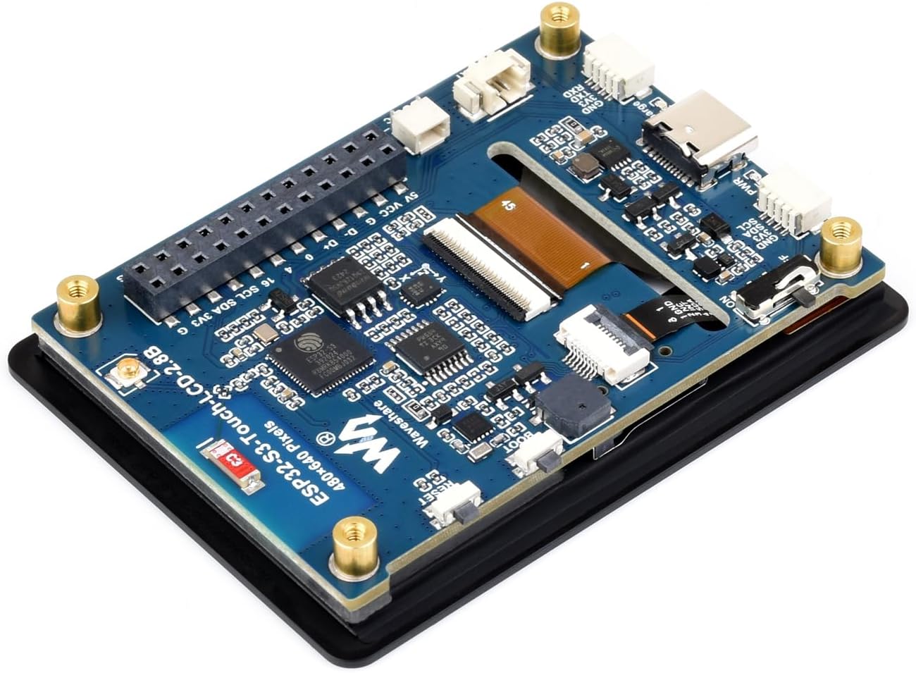
Figure 7: Supported development environments.
- ESP-IDF: The Espressif IoT Development Framework is the official development framework for ESP32 series chips. It provides a comprehensive SDK and tools, supporting IDEs like Eclipse and VSCode.
- Arduino IDE: A popular open-source electronic prototyping platform that offers a convenient and flexible environment for developing with ESP32 boards.
Refer to the waveshare product wiki or Espressif documentation for detailed guides on setting up these environments and programming the ESP32-S3.
9. Tiaki
Proper maintenance ensures the longevity and reliable operation of your development board.
- Te horoi: Keep the board clean and free from dust and debris. Use a soft, dry brush or compressed air. Avoid liquid cleaners.
- Te whakahaere: Handle the board by its edges to avoid touching components, especially the display surface. Static electricity can damage electronic components; use anti-static precautions when handling.
- Rokiroki: Penapenahia te papa ki te wāhi maroke, hauhautanga, kia matara atu i te rā tika me ngā pāmahana tino kino. Whakamahia he putea ārai-pūmau mēnā ka roa te penapena.
- Whakahaere Hiko: Always disconnect power before making physical changes to the board or connecting/disconnecting peripherals.
10. Te Raru
If you encounter issues with your ESP32-S3 2.8inch Display Development Board, consider the following:
- Kaore te Poari i te Whakamana:
- Verify the USB cable is securely connected and functional.
- Ensure the power source (USB port or battery) is providing adequate power (5V for USB, 3.7V for battery).
- Check the power indicator LED on the board.
- Whakaatu Kaore i te Mahi:
- Confirm the display ribbon cable is properly seated and secured.
- Ensure your firmware includes the correct display initialization code and drivers.
- Check for any physical damage to the display or its connector.
- Ngā Hapa Hōtaka:
- Verify that the correct board and port are selected in your IDE.
- Ensure USB-to-serial drivers are correctly installed.
- Try holding the BOOT button while pressing and releasing RESET to enter bootloader mode before uploading.
- Check for syntax errors or missing libraries in your code.
- Nga Take Hononga Wi-Fi/Nihokikorangi:
- Confirm the antenna is properly connected (if using external).
- Verify Wi-Fi credentials and network availability.
- Ensure your code correctly initializes and uses the Wi-Fi/Bluetooth modules.
11. Pūtāhui me te Tautoko
For warranty information, technical support, or further assistance, please refer to the official waveshare website or contact their customer service directly. Product documentation, examples, and community forums are often available on the manufacturer's support pages.


