1. Hua Neke Atuview
The ALIENTEK DM40 series is a professional 4.5-digit digital multimeter (59999 count Max) designed for fast and accurate measurements. It integrates the functions of a multimeter, oscilloscope, and signal generator into a single handheld device. Equipped with a high-precision 5ppm reference source, it ensures long-term stability and reliability for various applications, from automotive diagnostics to industrial and scientific use.
Nga waahanga matua
- Professional 4.5-Digit Multimeter: Offers 59999 counts maximum, ensuring high precision and accuracy.
- Integrated 3-in-1 Functionality: Combines a digital multimeter, oscilloscope, and signal generator.
- Ine Aunoa: Features auto mV/V and μA/mA/A gear measurement, eliminating the need for manual range switching.
- AC+DC Mixed Measurement: DM40B/C models can display both AC and DC components simultaneously for complex signal analysis.
- Ultra-Fast Continuity & Diode Test: Provides quick continuity checks and innovative diode function with multiple voltage drop measurements and distinct audible indicators.
- High-Resolution IPS Touchscreen: A 3.5-inch (480*320) screen offers fine display and convenient interactive control.
- Oscilloscope Specifications: 10-bit ADC, 50MHz sampling rate, and 10MHz bandwidth.
- Kaihanga Waitohu: Built-in function for generating various waveforms.
- Whakahaere Raraunga: Supports auto-measurement, relative measurement, data logging, data hold, and trend graph display.

Figure 1: The ALIENTEK DM40 series combines multimeter, oscilloscope, and signal generator functions.

Whakaatu 2: Neke Atuview of the DM40's high-quality features, including various measurement modes and display options.
2. He aha kei roto i te Pouaka
Please check the contents of your package upon receipt to ensure all items are present:
- ALIENTEK DM40A/B/C Digital Multimeter
- MP01 Test Leads (Red and Black)
- Probe Leads
- USB-C taura
- 1 x 9V Pūhiko (kei roto)
3. Tatūnga
3.1 Tāuta Pūhiko me te Whakatau
The DM40 series multimeter is equipped with an internal rechargeable battery. Ensure the battery is properly installed and charged before initial use. Connect the device using the provided USB-C cable to a suitable power source (e.g., USB wall adapter, computer USB port) for charging. A full charge provides over 10 hours of continuous operation for multimeter functions and 10 hours for oscilloscope functions.
3.2 Te hono i nga kaiarahi Whakamātautau
Proper connection of test leads is crucial for accurate and safe measurements. Refer to the following guidelines:
- Mō te nuinga o ngā inenga (Voltage, Resistance, Capacitance, Diode, Continuity, Frequency, Temperature), insert the black test lead into the COM (Common) port and the red test lead into the VΩHz tauranga.
- For current measurements (μA, mA, A), insert the black test lead into the COM port and the red test lead into the A mA μA port. Ensure the correct port is used to avoid damage to the device or circuit.
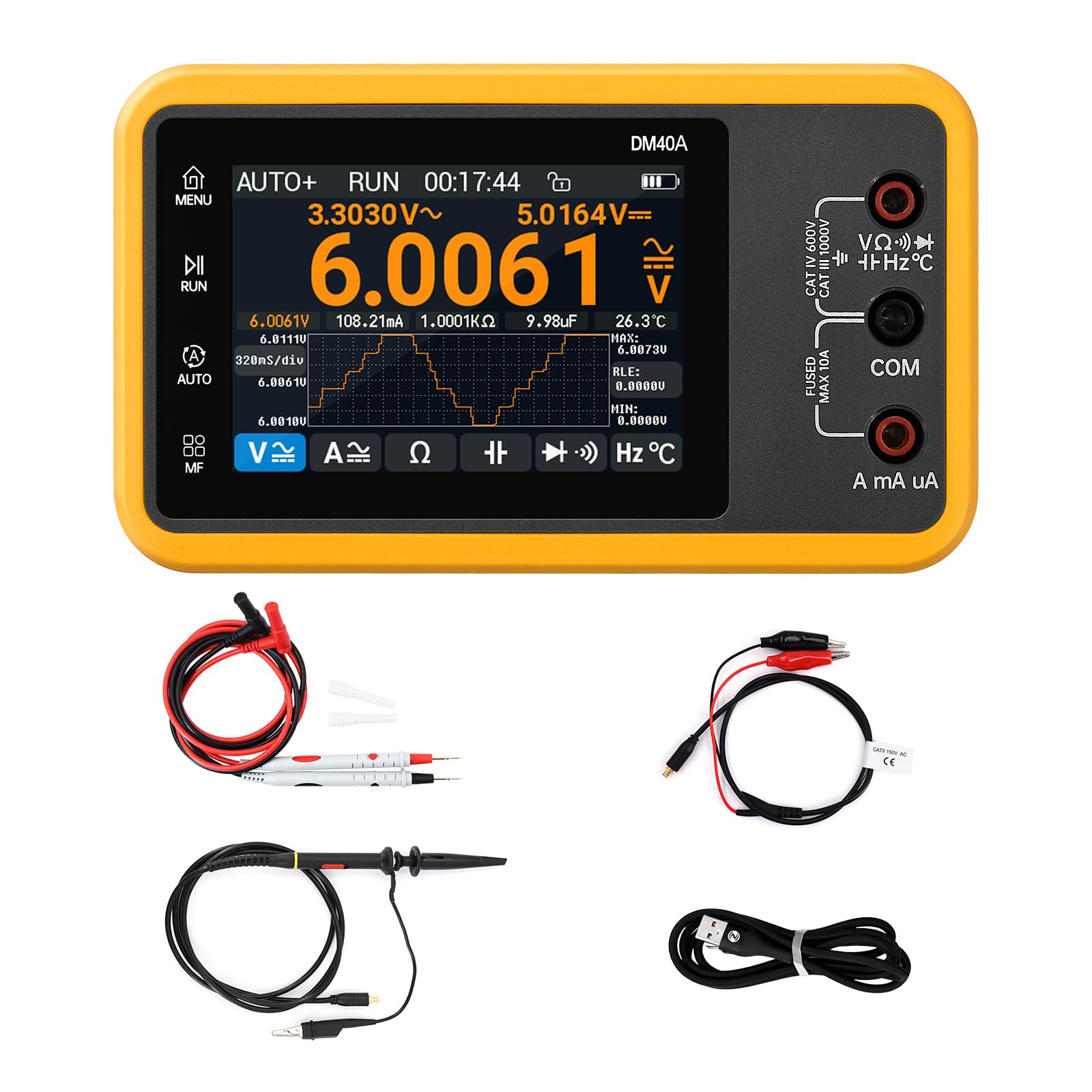
Figure 3: Proper connection of test leads for voltage, resistance, and other measurements.
4. Nga Tohutohu Whakahaere
4.1 Hiko / Whakaweto
To power on the device, press and hold the power button located on the side or front panel until the screen illuminates. To power off, press and hold the same button until the screen shuts down.
4.2 Automatic Measurement Mode
The DM40 series excels in its automatic measurement capabilities. In AUTO mode, the multimeter intelligently detects the type of measurement (DC/AC voltage, current, resistance, etc.) and automatically switches to the appropriate range. This feature significantly simplifies operation, especially for users who need to quickly assess various parameters without manual configuration.

Figure 4: Automatic voltage measurement in progress, showing auto-ranging capabilities.
4.3 Rererangitage Measurement (DC, AC, AC+DC)
Hei ine voltage, ensure test leads are connected to the VΩHz and COM ports. The multimeter automatically detects DC or AC voltage. For AC+DC mixed measurements (available on DM40B/C models), the device displays both AC and DC components simultaneously, providing a comprehensive view of complex signals. The small text on the top left and right of the display shows the AC and DC voltage values respectively.
Safety Warning: When the measured voltage exceeds 30V, the display font will turn red, and a red lightning symbol will appear, indicating potentially hazardous voltage levels. Always exercise extreme caution when working with high voltages.

Figure 5: AC+DC mixed measurement and trend chart display on the DM40 multimeter.
4.4 Current Measurement (DC, AC, AC+DC)
For current measurements, insert the red test lead into the A mA μA port and the black lead into the COM port. Use the current range button to cycle through DC, AC, or AC+DC measurement modes. The device supports automatic range switching for current, from microamperes (μA) to ampere (A).
4.5 Whakatautau Diode
The innovative diode test function allows for precise voltage drop measurement across diodes. The device provides distinct audible indicators for different voltage drop ranges, making it easy to identify diode characteristics. This test is performed with high accuracy.

Figure 6: Diode test function displaying voltage drop measurements.
4.6 Whakamātautau Tonu
The ultra-fast continuity test allows you to quickly check for open or closed circuits. An audible beep indicates a continuous path, while no sound suggests an open circuit. This function is highly responsive, with quick measurements typically less than 1 microsecond.
4.7 Oscilloscope Function
The integrated oscilloscope function provides advanced waveform analysis capabilities. With a 10-bit ADC, 50MHz sampling rate, and 10MHz bandwidth, it allows for detailed observation of electrical signals. Key features include various time scales, vertical scales, coupling options (AC/DC), and mathematical functions like FFT/ABS.
4.8 Kaihanga Waitohu
The built-in signal generator can produce various waveforms, including sine, sawtooth, triangular, and square waves. This is useful for testing circuits, calibrating other equipment, or generating specific signals for experimental setups. Frequencies range from 1Hz to 10MHz depending on the waveform type.
4.9 IPS Touchscreen Interaction
The 3.5-inch IPS touchscreen provides an intuitive interface for navigating menus, selecting functions, and viewing measurement data. Its high resolution (480*320) ensures a clear and detailed display, enhancing user experience.

Figure 7: The high-resolution 3.5-inch IPS touchscreen for clear display and interaction.
4.10 Data Logging and Trend Graph
The DM40 supports essential data management features such as data logging, data hold, and relative measurement. The trend graph function allows users to visualize measurement data periodically, with adjustable time bases (160ms/320ms/640ms), aiding in the observation of signal changes and stability over time.
4.11 Ataata Hua Whaimana
Video 1: This video demonstrates the voltage and current measurement capabilities of the ALIENTEK DM40 Digital Oscilloscope Multimeter, including auto-ranging, AC/DC measurements, and safety warnings for high voltage.
5. Tiaki
5.1 Te horoi
To maintain the device's performance and appearance, wipe the exterior with a soft, damp kakahu. Kaua e whakamahi i ngā kaihoroi whakakoi, ngā whakarewa, ngā matū kino rānei, nā te mea ka kino pea ēnei ki te kiriasing or screen. Ensure the device is powered off and disconnected from any power source before cleaning.
5.2 Tiaki Pūhiko
The DM40 series features a high-capacity rechargeable battery designed for over 10 hours of use. For optimal battery life and performance:
- A ape i te tino tuku i te pākahiko i nga wa katoa.
- Charge the device regularly, even if not in constant use.
- Whakaorangia te taputapu ki te waahi makariri, maroke ki te kore e whakamahia mo te wa roa.
- The multimeter communication is fully isolated, ensuring safety during operation and charging.
5.3 Rokiroki
Store the multimeter in a dry, dust-free environment away from direct sunlight, extreme temperatures, and high humidity. Keep it away from strong magnetic fields and corrosive gases. If storing for a long period, ensure the battery has a partial charge (around 50%) to prolong its lifespan.
6. Te Raru
This section addresses common issues you might encounter with your ALIENTEK DM40 multimeter.
6.1 "OL" Display (Overload)
If the display shows "OL" (Overload), it indicates that the measured value exceeds the current range or maximum input limit of the selected function. To resolve this:
- If in manual range mode, switch to a higher measurement range.
- Ensure the input is within the device's specified maximum limits for the selected function.
- For current measurements, verify that the test lead is inserted into the correct current measurement port (A mA μA) and not the voltage tauranga.
6.2 No Reading or Inaccurate Readings
- Check Test Lead Connections: Ensure the test leads are securely inserted into the correct ports on the multimeter and are making good contact with the circuit being measured.
- Taumata Pūhiko: Verify that the battery is sufficiently charged. A low battery can affect measurement accuracy.
- Correct Mode Selection: Confirm that the appropriate measurement mode (e.g., DC Voltage, AC Current, Resistance) is selected for the task.
- Damaged Leads: Inspect the test leads for any signs of damage (e.g., frayed wires, broken insulation). Replace damaged leads immediately.
6.3 Kaore te Pūrere i te hiko
- Utu Pūhiko: Connect the multimeter to a power source using the USB-C cable and allow it to charge for some time.
- Pātene Hiko: Kia tika te pehi me te pupuri tika i te paatene hiko.
7. Whakatakotoranga
Detailed technical specifications for the ALIENTEK DM40A/B/C Digital Multimeter are provided below.
7.1 Nga korero taketake
| Tawhā | Uara |
|---|---|
| Tauira | DM40A/B/C |
| Mata | Full Touch 3.5" IPS (480*320) |
| Ora Pūhiko | 12H (Multimeter) / 10H (Oscilloscope) |
| Ahu | 5.5 x 3 x 1 inihi (140 x 83 x 25 mm) |
| Taumaha Tūemi | 1.89 pauna (260g) |
| Atanga | USB-C, MCX, Banana Seat |
| Puna Mana | Pūhiko (kei roto te pākahiko 9V 1) |
| Momo Whakatakotoranga | CE, FCC |
7.2 Oscilloscope / Signal Generator Technical Parameters
| Tawhā | Uara |
|---|---|
| Sample Reiti | 50MSa / s |
| Aratuku | 10MHz |
| Te Maharahara Hohonu | 64Kpts |
| Tauine Wā | 100ns ~ 50s |
| Tauine Poutū | 10mV ~ 10V/div (X1) |
| Whakatau | 10Moka |
| Te hono | AC/DC |
| Impedance Tāuru | 1MΩ |
| Aratau Waahi | Aunoa/noa/Tatahi |
| Aratau Horoi | Te Hinga/Hinga |
| Nga Mahi Pangarau | FFT/ABS |
| Nga Momo Ngaru | Sine, Tapawhā, Tapatoru, Niho kani |
7.3 Measurement Ranges and Accuracy
| Mahi | DM40A Range | DM40B Range | DM40C Range | Tika |
|---|---|---|---|---|
| DC Voltage | 400mV/4V/40V/400V/1000V | 500mV/5V/50V/500V/1000V | 600mV/6V/60V/600V/1000V | ±(0.03%+5d) |
| AC Voltage | 400mV/4V/40V/400V/750V | 500mV/5V/50V/500V/750V | 600mV/6V/60V/600V/750V | ±(0.3%+15d) |
| DC Naianei | 400μA/4000μA/40mA/400mA, 4A/10A | 500μA/5000μA/50mA/500mA, 5A/10A | 600μA/6000μA/60mA/600mA, 6A/10A | ±(0.15%+5d) (μA/mA), ±(0.2%+5d) (A) |
| AC o nāianei | 400μA/4000μA/40mA/400mA, 4A/10A | 500μA/5000μA/50mA/500mA, 5A/10A | 600μA/6000μA/60mA/600mA, 6A/10A | ±(0.5%+15d) (μA/mA), ±(0.75%+15d) (A) |
| Ātete | 400Ω/4KΩ/40KΩ/400KΩ/4MΩ/40MΩ | 500Ω/5KΩ/50KΩ/500KΩ/5MΩ/50MΩ | 600Ω/6KΩ/60KΩ/600KΩ/6MΩ/60MΩ | ±(0.1%+5d) (Ω), ±(0.2%+10d) (MΩ) |
| Te kaha | 4nF/40nF/400nF/4μF/40μF/400μF/4mF | 5nF/50nF/500nF/5μF/50μF/500μF/5mF | 6nF/60nF/600nF/6μF/60μF/600μF/6mF | ±(2.5%+30d) (nF-μF), ±(3.5%+30d) (mF) |
| Auautanga | 10Hz ~ 40MHz | 10Hz ~ 50MHz | 10Hz ~ 60MHz | ±(0.01%+5d) |
| Te pāmahana | -40°C ~ 1000°C (-40°F ~ 1832°F) | -40°C ~ 1000°C (-40°F ~ 1832°F) | -40°C ~ 1000°C (-40°F ~ 1832°F) | ±(1.0%+5°C) (probe range -20°C~300°C), ±(1.5%+5°F) |
| Tonu | 0Ω ~ 1KΩ | 0Ω ~ 1KΩ | 0Ω ~ 1KΩ | ±(0.2%+5d) |
| Diode | 0V ~ 3.0V, 0Ω ~ 1KΩ | 0V ~ 3.0V, 0Ω ~ 1KΩ | 0V ~ 3.0V, 0Ω ~ 1KΩ | ±(1%+5d) |
7.4 Special Features Comparison
| Āhuahira | DM40A | DM40B | DM40C |
|---|---|---|---|
| Maximum Display (Counts) | 39999 | 49999 | 59999 |
| Aratau AUTO | ✓ | ✓ | ✓ |
| TRMS | ✓ | ✓ | ✓ |
| Whakautu auau | 10KHz | 10KHz | 10KHz |
| Ine AC+DC | ✓ | ✓ | |
| Duty Cycle Measure | 5%~95% | 5%~95% | 5%~95% |
| Pupuri Raraunga (HOLD) | ✓ | ✓ | ✓ |
| Relative Measurement (RLE) | ✓ | ✓ | ✓ |
| Extreme Value Measurement (Max/Min) | ✓ | ✓ | ✓ |
| Trend Chart (WAVE) | ✓ | ✓ | ✓ |
7.5 Signal Generator Waveform Parameters
| Tawhā | Waiariki | Ngaru niho kani | Triangular Wave | Ngaru Tapawha |
|---|---|---|---|---|
| Kaupapa | DM40A/B/C | |||
| Auautanga | 1Hz ~ 50KHz | 100KHz ~ 10MHz | ||
| Ampahuru | 0.5V ~ 3.0Vpp | 3.0Vpp | ||
| Huringa Mahi | Kaore e taea te whakarite | 0 ~ 100% | ||
8. Nga korero haumaru
Me ū tonu ki ngā tūpatotanga haumaru e whai ake nei hei aukati i te whara whaiaro, i te kino ranei o te mita maha, taputapu ranei kei te whakamatautauria.
- Whakatau Haumaru: The DM40 series is rated for CAT IV 600V and CAT III 1000V. Always ensure your measurements are within these categories and voltage rohe.
- Maximum Limits: Kaua e ngana ki te ine voltages or currents that exceed the specified maximums for each range. Refer to the specifications table.
- Isolated Communication: The multimeter features fully isolated communication, enhancing safety during operation.
- Tirohia ngā Arataki Whakamātautau: Always inspect test leads for any signs of damage (e.g., cracks, frayed insulation) before each use. Replace damaged leads immediately.
- He kaha Voltage Whakatupato: I te ine voltages above 30V, the device will display a red warning on the screen. Exercise extreme caution and use appropriate personal protective equipment.
- Proper Port Usage: Always connect test leads to the correct input jacks for the desired measurement. Incorrect connections can lead to damage or injury.
9. Pūtāhui me te Tautoko
9.1 Mahere Tiaki
Optional protection plans are available to extend the coverage of your ALIENTEK DM40 Digital Multimeter:
- Mahere Tiaki Tau 3: Ka whakarato i te kapinga roa mo nga tau e toru.
- Mahere Tiaki Tau 4: Provides extended coverage for four years.
- Tiaki Whakaoti: A comprehensive plan that covers all eligible past and future purchases (available with monthly billing).
Mō ētahi atu kōrero, tirohia ngā tikanga me ngā herenga motuhake o ia mahere tiaki.
9.2 Tautoko Kiritaki
For technical assistance, warranty claims, or any further inquiries regarding your ALIENTEK DM40 Digital Multimeter, please contact ALIENTEK customer support through your purchase platform or visit the official ALIENTEK website for contact information. Our support team is available to help you with any questions or issues you may have.


